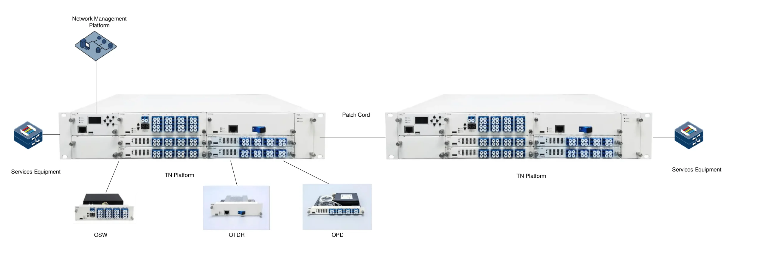
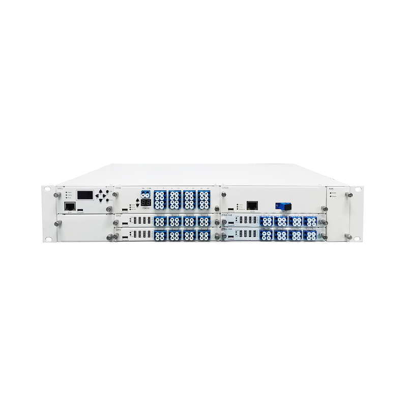
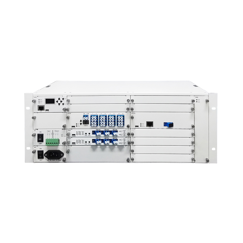
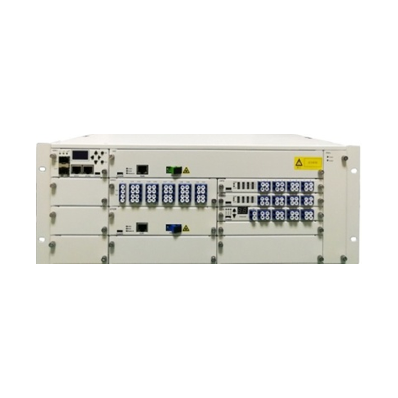
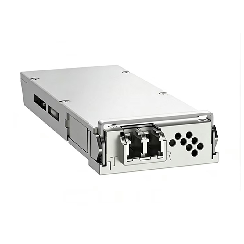
The OTDR Subsystem of the TN2000 Optical Cable Monitoring System is an integrated optical fiber monitoring solution that adopts 1U/2U/4U standardized chassis as its hardware carrier. It integrates a monitoring unit RTU consisting of SC, OTDR, OSW, OPD, LSU and other hardware components: the SC enables data interaction with the monitoring center, the OTDR module detects the loss and connection status of optical fiber links, the OSW is built-in with a 64-channel optical switch to realize routing switching and selection for multiple test optical fibers, and the OPD is responsible for monitoring changes in optical power. Specifically designed for DWDM systems and optical cable & fiber monitoring scenarios, the OTDR Subsystem can achieve optical fiber characteristic detection, fault location and resource management throughout the entire process of optical cable construction, maintenance and monitoring. Boasting high adaptability, high detection accuracy, easy operation and maintenance as well as high scalability, it has become a core device for the full-life-cycle management of optical fiber links in optical communication networks. A single set of the OTDR Subsystem can monitor up to 64 optical fiber links simultaneously and be flexibly adapted to the monitoring requirements of star, ring and chain optical fiber networks.
Monitored metrics include: total fiber link loss; position and lossof fusion splices; position and loss of
connectors (adapters); position and loss of fibers subject to extruusion or bending.
The fiber health check can be performed automatically on a scheduled basis or manually.
It enables comparison of performance data over time, facilitating timelydetection and elimination of
potential fiber performance issues.
Provides 24/7 real-time monitoring of fiber status.
In the event of a fiber break: the monitoring software triggers audiblle and visual alarms; the fault location is
displayed on the software's map interface; relevant personnel are notified of the alarm and fault location via
SMS and email.
Enables full-coverage monitoring of optical cables across the backborne, convergence and access layers of
the network, and is compatible with devices from various manufactureers.
Fiber routes, as well as the locations of equipment rooms, ODFs and nnetwork elements, are displayed
intuitively on the map.
In case of a fiber break, the fault location is marked on the map, withfault status indicated by distinct color
coding.
| Parameter | Specification |
|---|---|
| Dynamic Range (dB) | 30 / 35 / 40 |
| Wavelength (Optional) | 1310 / 1550 / 1625 nm (±20 nm) |
| Fiber Type | 9/125 µm Single Mode Fiber (SMF) |
| Pulse Width | 5 ns, 10 ns, 20 ns, 40 ns, 80 ns, 160 ns, 320 ns, 640 ns, 1.28 µs, 2.56 µs, 5.12 µs, 10.24 µs, 20.48 µs, Auto Control |
| Event Dead Zone | ≤ 2 m |
| Attenuation Dead Zone | ≤ 10 m |
| Minimum Sampling Resolution | 0.25 m |
| Maximum Sampling Points | 32k |
| Distance Accuracy | ± (1 m + 5 × 10⁻⁵ × distance + sampling resolution) |
| Connector | Letter of Credit* |
| Distance Measurement Length | 120km |